THIS POST HAS BEEN UPDATED
After installing my orange pi zero. I tried to use my board the reencode some video file that use xvid/ac3 to x264/aac with the ffmpeg linux command.
The problem was that it took more than two hours at 100% cpu usage on the 4 cores to reencode the video, during that time the cpu was getting instantly too hot and, as a result, was heavily throttling . I tried to use a radiator, and it significantly reduced the amount of throttling but it was not eliminating it, since eventually the cpu reached pretty high temperature.
I decided to add a fan to blow on the radiator to reduce even further the cpu temperature.
I didn’t want the fan to be running all the time so I decided to use the gpio function of my board to control the state of a pin to start and stop a fan.
The problem is that the logic levels sent by the gpio is 3.3v which is much to low to start the fan i own.
My fan is a 12v fan, but it turns out that it can run at 5v, it just have a lot of trouble starting, most of the time when I put 5 v on the fan, I just see a very small movement, and then nothing, I just have to give a little push, and then it will start
Of course, this is not going to be OK. I must find a way to start that fan without that initial push.
To send 5v instead of 3.3v to the fan I used a PNP transistor that will be controlled by the 3.3v signal.
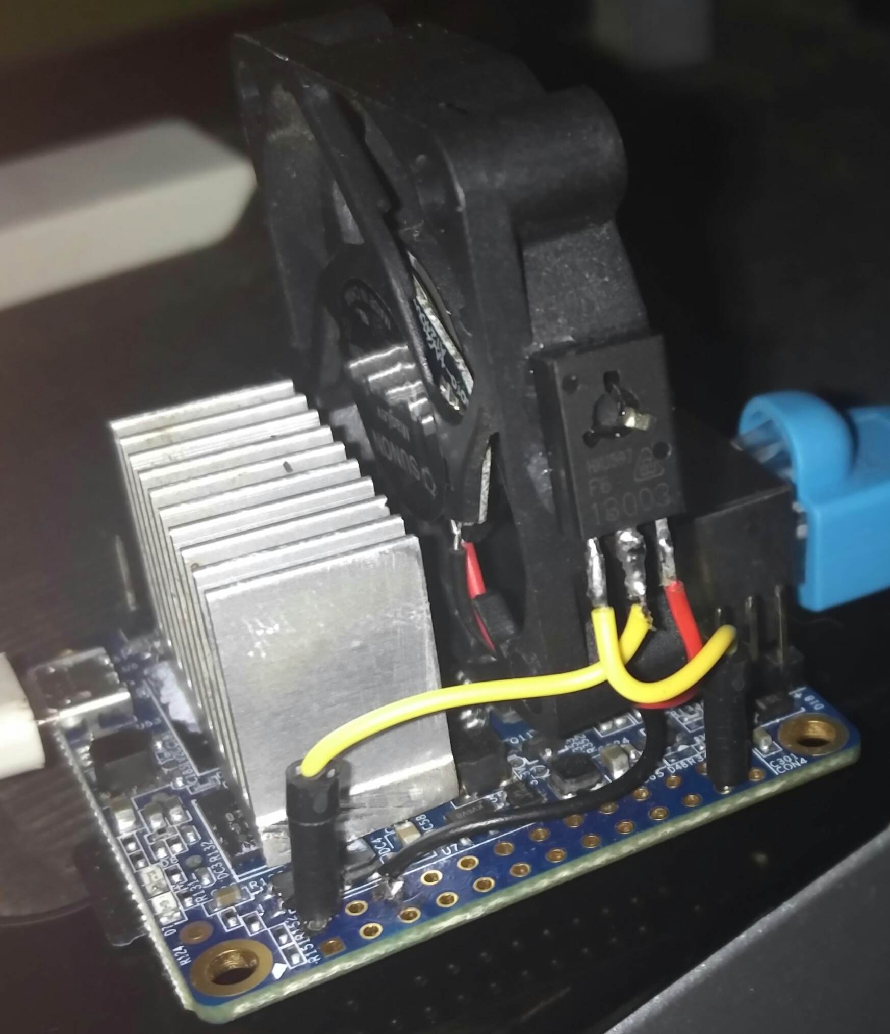
As you can see on the photo, the pin one of the PNP transistor is wired to a GPIO pin, the pin 2 is wired to the pin 2 of the board which provide constant 5v,and then the pin 3 is wired to the the red wire of the fan.
The black fan wire is connected to the pin number 6 of the board.
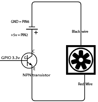
Here is a little schematic of the wiring.
To control the gpio I used wiringpi program that I found at this URL
At first I tried to use the gpio pin number 23 but, for some reason I failed to change the state of that pin using the wiring pi library.

I then chosed to use the pin number 7 which is named GPIO.7 in the “gpio readall” command.
First I configured the pin 7 as an output using that command
gpio mode 7 out
Then i use that command to set pin 7 at logic level 1 (3.3v)
gpio write 7 1
But even with all that, my fan still needed a little push to start turning.
After a good afternoon where I considered buying a cheap and small 5v fan on one of the classic Chinese website, i remarked that if my control GPIO pin was not soldered and I disconnected and reconnected very rapidly the control wire, the fan was starting every time.
The idea of a bash script exploiting this fact was born.
Here is the script that works for me every time!
#!/bin/bash
gpio mode 7 out
i=0
while (($i < 10))
do
gpio write 7 1
sleep .1
gpio write 7 0
sleep .05
i=$(($i+1))
echo $i
donegpio write 7 1
This script put the pin 7 in output mode, then switch the state of pin 7 rapidly provoking the startup of the fan. At the end of the script the pin 7 is left in the 1 state.
To be sure the fan started, I usually launch this script 3 times, but it’s overkill and one time is enough most of the time.
When I want to stop the fan, I just launch the command
gpio write 7 0
And the fan stop immediately,
Now creating a script that launch automatically the fan when the cpu get above a predefined temperature is going to be extremely easy, I will describe it in another article.
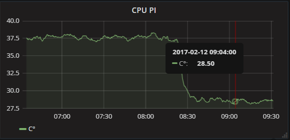
Even if the fan is turning very very slowly , it does have a very significant effect on cpu temperature
Hi! It is good to see you attempts to cool down processor. Will you try to integrate your experiments in the fancontrol (sudo apt-get install fancontrol)
Unlikely , i don’t want the added complexity , the current state is very simple and efficient
I’m surprised that worked. Your fan should not get more voltage than the GPIO output minus the transistor’s B-E drop, that is 3.3V – 0.6ish V, around 2.7 volts (But it will amplify the current).
To wire it correctly with an NPN transistor as a switch like this, your fan should be between the transistor’s collector pin and the +5 volt. It won’t get exactly 5V, but a little bit lower due to voltage drop over the transistor’s C-E pins, depending on the transistor. Also, important, use a resistor between the GPIO output and the base pin on the transistor. At least a few 100 ohms, or maybe a few k-ohms, hard to say, depends on the transistor. And the output current capability of the GPIO. Which, incidentally, I don’t know what is, and I’m completely new to the Orange Pi Zero btw (literally just logged into it for the first time, and my lacking google-fu about GPIO pins brought me here lol).
In short, just google “transistor as a switch”, and you should be set.
You are 100 % right!
I was only getting 2.6v
Can you please explain me the purpose of the resistor between the gpio output and the transistor gate?
please see the link on top : this post has been updated
The resistor between the GPIO and the Gate is known as a current limiting resistor. It’s there to ensure you don’t exceed the current supply capabilities of the GPIO pin, typically 5-20ma.